- Home
- Technical Article # 2 The Diesel Fuel System & Inlet Line
Technical Article # 2 The Diesel Fuel System & Inlet Line
THE DIESEL FUEL SYSTEM AND INLET LINE
Improving the Fuel System for Maximum Efficiency and Horsepower
Article number two is finally complete! It took several days to compile the technical information, photographs and details for this article. The actual writing process was very enjoyable. Please accept my apology for not delivering the technical article sooner. Thank you for your patience.
This summer has been incredibly busy with all the diesel events. Late summer and early fall required countless tests with the AirDog II 165 and P pump flow numbers. Our goal was to solve the low fuel pressure problem, at full power, with the AirDog or FASS and Bosch P7100 combination. Problem solved!
You will remember from Tork Tool article number one that the Cummins lift pump is a proven, solid and reliable transfer pump. We left off with the low efficiency numbers of the Cummins fuel system, and promised you ways to improve it's efficiency, and utimately increase your horsepower and torque numbers.
My Original Intention Was to Focus Specifically
on the Cummins Fuel System
We received hundreds of email replies from the first article. The comments ranged from “good technical article, add my name to the list to receive the entire series” to questions like “how do I increase the efficiency of my Carter lift pump?” The questions and comments have changed the focus of the article series....a little. Many readers of the first article asked technical questions about their Cummins performance fuel systems. This lead us to merge the original concept of the Bosch P7100 fuel system, with how to design the fuel system for maximum HP and torque. The "new" article series will incorporate our trusty stock Cummins 12V and performance diesel fuel systems together.
Where is the Problem and How Do we Fix It?
We already calculated the fuel flow capability of the Cummins lift pump in article number one. Under ideal conditions, it can pump 1.48 GPM at 2500 RPM. Of course, it doesn't come close, at .52 GPM and 35% efficiency. Why?
We are going to dissect the entire fuel system, find the problems and learn the formulas to size the components for a killer race engine. These principles will also help increase the efficiency of your stock Cummins diesel also. The hydraulic principles and formulas will work on a Cummins, Powerstroke, Duramax diesel or any HP gas engine. I promise that the formulas are very easy to learn.
Hydraulic Principle Number One
The inlet, or commonly called the intake or suction line, is critically important to the efficiency of any system, whether it's a hydraulic or fuel system. The suction line is defined as a tube, hose or pipe that runs from the storage tank to the intake side of the pump. If the inlet (suction) size is wrong, the entire system will suffer with reduced power because the overall efficiency is reduced. It would be similar to buying the best race parts, porting the heads, adding a high dollar intake and exhaust and using the stock cam. The cam is not matched to the other components and the entire engine suffers from poor performance. There is no better example, of a less than adequate design, than the 94-98 Dodge Cummins. Let's have a look.
How do we size the suction line? I've seen several examples of expensive sled pullers using an undersize inlet line which will affect the horsepower produced by that diesel. A simple observation of the pump and line size combination, shows that no calculations were used in the design.
There are several “rules of thumb” that will get you in the ball park. I prefer to use calculations that will work for a 5HP log splitter to a 1500HP Cummins sled puller.
First Rule of Thumb
This rule is super important. Get it wrong and it will cost you power! The inlet line must be sized to create fluid flow velocity of 2 to 4 feet per second.
Let's look at a formula that looks difficult, but it's NOT. After you work with it a few times, it will become second nature. We will break it down to make it very easy to understand.
Velocity (feet per second) = GPM (gallons per minute)
3.117 X Area of line (square inches)
Let's do a few practice calculations before we look at our Cummins system, to see how it compares to proven hydraulic principles. You are building a high performance Cummins diesel sled puller. The diesel shop that built your engine, sold you a pump that will feed your Bosch P7100 injection pump at a steady 50 PSI. Your HP racing fuel pump is rated at 10 GPM and you choose an inlet line that is 3/4” inside diameter (.750 ID) That sounds about right, or does it?
The first thing we do is find the area of the .750 ID suction line.
Pi X R² = area in square inches. PI is always 3.1416 and the radius of .750 is .375 (half the diameter) So, 3.1416 X .375 X .375 = .44 square inches.
Now let's plug that number into the formula to find the velocity.
10 GPM 10
3.117 X .44 (area of .750 line) = 1.37 = 7.3 feet per second
The flow velocity of 7.3 is way too fast and will cost you power! You must keep the inlet velocity between 2 and 4 feet per second to produce maximum horsepower. This example is a horrible design and your pump will wear out much sooner from cavitation! Cavatation are air bubbles that collapse and erode pump components. It is similar to sand blasting except the media is a fluid.
How about increasing the ID to 1 1/4” or 1.250 (radius is .625) to see if that helps. First, find the area. 3.1416 X .625 X .625 = 1.227 In² or round up to 1.23 square inches.
10 GPM 10
3.117 X 1.23 (area of 1 1/4” line) = 3.83 = 2.61 feet per second
By doing the numbers on the inlet line, we found that a ¾ ID line is way too small and the 1 1/4” is perfect. Remember the inlet line is the back bone of the entire fuel system. Taking the time to do it right makes horsepower!
HOW DOES THE CUMMINS COMPARE?
How does the Carter lift pump and its inlet line rate? You are going to be surprised by the final result! The Cummins lift pump has a calculated flow rating of 1.47 GPM at 2500 RPM. The inlet line is a 3/8" SS tube with a wall thickness of .030. The ID is .375 OD - .030 - .030 = .315 inside diameter. Convert the .315 inside diameter to area. 3.1416 (Pi) X .158 (radius) X .158 = .078 square inches. Let's plug that number into the formula to see what we get.
1.47 GPM 1.47
3.117 X .078 (area) = .243 = 6.05 feet/second velocity
You are way ahead of me when you say that's way too fast. The diesel fuel is flowing 6 feet, every second, from the fuel tank to the Cummins lift pump, at 2500 RPM. Do you think that the high velocity affects the efficiency of the Cummins lift pump? You bet it does!! First rule of thumb states 2 to 4 feet/second. Obey this rule for peak power production.
There's Another Problem That Increases
the Velocity Even More
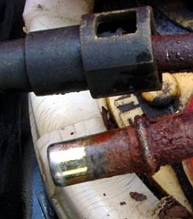 The Dodge Cummins has an additional design flaw that makes the velocity problem worse, as you will see! There are two quick connect fittings on the Dodge. One is located above the fuel sender on the tank, and the other is upstream of the lift pump by about 10”. The SS inlet line is swaged or necked down to accept the OEM quick connect fitting. The radiused end eases the tube into the fitting so the O ring is not sheared and creates an air leak.
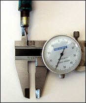 The swaged ends add two orifices into the inlet line and increases the velocity of the fuel. The actual inside diameter of the swaged tube is .260 (.053 area) How will that affect the velocity of of the fuel? Let's see.
1.47 GPM 1.47
3.117 X .053 = .165 = 8.9 ft/sec velocity
At two places in the inlet line, the velocity increases to 8.9 ft/sec which is a 47% increase in velocity. NOT GOOD! You can create the same problem using hydraulic tube and hose barb fittings. The ID will be smaller and increases the velocity.
Other Design Considerations
In addition, you have to consider three additional principles to size the inlet line correctly.
(1) If the system will be exposed to winter weather, the fluid or fuel will thicken, as the temperature drops. Size the inlet line close to 2 feet per second for cold weather.
(2) Keep the run from the tank to the pump as short as possible. If race rules permit, get the tank close to the pump. The long bed,extended cab Dodge Cummins has the tank 10 feet from the lift pump. At that distance, size the intake line at 2 feet/second.
(3) In high efficiency hydraulic systems, the fluid tank is located above the inlet port to the pump. The fluid is always at a positive pressure when it enters the pump. Our Dodge Cummins fuel tank is below the pump inlet by 18" inches. Size for 2 feet per second under this condition.
Obviously, the suction line has worked for years and presented no real problem, except to put an added load on the Cummins lift pump and severely lower the efficiency. I believe that Chrysler sized the inlet line at 3/8" for two reasons. The first is cost reduction and the second could be a horsepower limiting device which would make the rest of the engine and drive line last longer.
What is the Right Size Inlet Line for Our Cummins Lift Pump?
Let's use another formula to find the correct inlet line size for our particular application. You will see that is a variant of the formula we used already.
Area (square inches) = GPM X .3208
Desired velocity in ft/sec
Let's shoot for 2 ft/second because your truck is winter driven and it's a long bed, extended cab truck.
1.47 GPM X .3208 .47
2 (desired velocity) = 2 = .235 square inces of area - (not diameter)
If we use a 5/8” tube with a .030 wall, we get a 9/16" ID which equals .246 square inches. This line size will give us 2 ft/sec velocity. The 5/8” OD tube is a far cry from the OEM 3/8” tube. Remember, this size inlet line is good for 2500 RPM, only.
What if your truck is located in Texas and it's a short bed, regular cab truck. We will figure for 4 ft/sec velocity.
1.47 X .3208 = .47 = .118 area
4 (desired velocity) 4
The .118 area is equal to slightly larger than 3/8” ID (.388 ID). That's with no necked down ends and sharp corners. Remember, we sized this for 1.47 GPM at 2500 RPM. If you put a 4000 RPM governor kit in your Bosch P7100 injection pump, the 3/8” diameter inlet line would be TOO small! You will have to calculate the GPM flow at 4000 RPM and refigure the calculations for the higher calculated flow rate.
4000 RPM - Now What Size Do We Use?
Referring to article number one, we calculated the fuel flow, at 4000 RPM, to be 2.36 GPM. In sizing the line, you have to use the calculated flow potential of the pump, NOT it's actual flow rate. The idea is to size the entire system to match the capability of the pump in order to maximize efficiency. Increased efficiency equals more power.
This time, we will shoot for the middle velocity of 3 feet per second. Take a guess as to the right size intake line that is required.
2.36 GPM X .3208 .76
3 (desired velocity) = 3 = .252 square inch area
.252 square inches translates into an inside diameter of .570. A 5/8" OD X .030 wall tube would work just fine. .625 OD -.030 - .030 = .565 ID. Do you see the effect of RPM when using a mechanical pump? As the RPM's go up. the inlet line must be increased to maintain 2 to 4 feet per second velocity. When you use an electric pump, you simply use the rated flow number supplied by the manufacturer.
Second Rule of Thumb
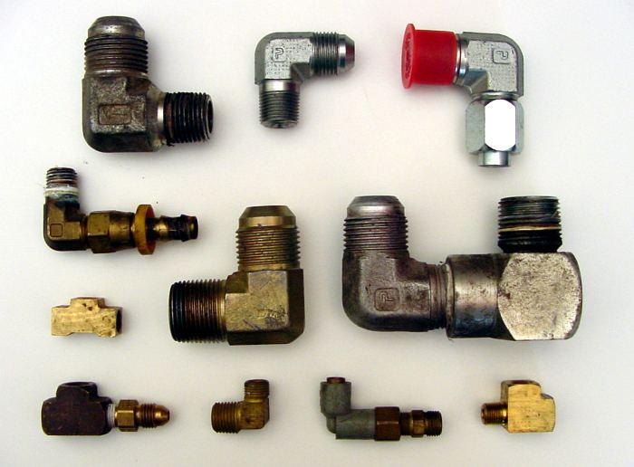
In a custom fuel system, watch out for fittings that destroy the laminar flow of the fluid. Especially avoid fittings with sharp 90 degree corners as these fittings destroy the smooth flow and make the fluid turbulent! I realize that in some applications the use of these fittings is manditory because of space limitations. The perfect example in on the top of the fuel sender.
 Loading... Please wait...


